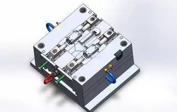
Injection molds are tools used to produce plastic products; they also give plastic products a complete structure and precise dimensions. The structure of the injection mold and the quality of the mold processing directly affect the quality of the plastic product and production efficiency.
The most common and most frequently occurring causes of injection mold failures in injection mold production and plastic product production practices and their troubleshooting methods are detailed below:
Difficulty in removing the material from the gate
During the injection molding process, the gate stuck to the sprue bushing and was difficult to remove. This caused cracks and damage to the product during mold opening.
Furthermore, the operator had to use the tip of a copper rod to knock the nozzle loose before demolding, severely impacting production efficiency. This failure was primarily caused by poor finish on the gate taper and knife marks along the inner circumference.
Secondly, the material is too soft, and the small end of the tapered hole is deformed or damaged after a period of use, and the curvature of the nozzle spherical surface is too small, causing the gate material to produce a rivet head here.
The tapered hole of the gate sleeve is difficult to process, and standard parts should be used as much as possible. If you need to process it yourself, you should also make or purchase a special reamer.
The tapered hole needs to be ground to Ra0.4 or above. In addition, a gate pull rod or gate ejection mechanism must be set.
Guide column damage
The guide pin mainly plays a guiding role in the mold to ensure that the molding surfaces of the core and the cavity do not collide with each other under any circumstances. The guide pin cannot be used as a force-bearing part or a positioning part.
In the following cases, the dynamic and fixed molds will generate huge lateral offset forces during injection:
(1) When the wall thickness of the plastic part is uneven, the material flow rate through the thick wall is high, generating greater pressure there;
(2) The side of the plastic part is asymmetrical, such as the opposite sides of the mold with a stepped parting surface are subjected to unequal counterpressure.
Large mold
Due to different filling rates in all directions and the influence of the mold’s own weight during mold loading, the dynamic and fixed molds will offset.
In these cases, the lateral offset force during injection will be applied to the guide pins, causing roughness and damage to the guide pins during mold opening. In severe cases, the guide pins will bend or cut off, or even prevent the mold from opening.
To address these issues, high-strength locating keys are added to the mold parting surface, one on each side. The simplest and most effective method is to use cylindrical keys. Perpendicularity between the guide pin hole and the parting surface is crucial.
During machining, the movable and fixed molds are aligned and clamped, then bored in one go on a boring machine. This ensures concentricity between the movable and fixed mold holes and minimizes perpendicularity errors.
Furthermore, the heat treatment hardness of the guide pins and guide sleeves must meet design requirements.
Bending of the moving plate
During injection, the molten plastic in the mold cavity generates a significant back pressure, typically between 600 and 1000 kg/cm. Moldmakers sometimes neglect this issue, often changing the original design dimensions or replacing the movable platen with low-strength steel.
In molds that use ejector pins, the large span between the two side seats causes the platen to bend during injection.
Therefore, the movable formwork must be made of high-quality steel with sufficient thickness. Low-strength steel plates such as A3 must not be used.
When necessary, support columns or support blocks should be installed under the movable formwork to reduce the thickness of the formwork and improve the bearing capacity.
The ejector pin is bent, broken or leaking
Homemade ejector pins are of good quality, but the processing cost is too high. Standard parts are now generally used, resulting in poor quality. If the clearance between the ejector pin and the hole is too large, material leakage may occur. However, if the clearance is too small, the ejector pin may expand and become stuck during injection due to the increased mold temperature.
Even more dangerous is that the ejector pin may break after being pushed out a certain distance. As a result, the exposed portion of the ejector pin cannot be reset during the next mold closing, potentially damaging the die.
To solve this problem, the ejector pin is reground, leaving a 10-15mm fit section at the front end of the ejector pin and grinding the middle part down by 0.2mm.
After assembly, all ejector pins must be strictly checked for fit clearance, which is generally within 0.05-0.08mm to ensure that the entire ejector mechanism can move forward and backward freely. 6. Poor cooling or water leakage
The cooling effect of the mold directly affects the quality and production efficiency of the product. For example, poor cooling can cause large or uneven shrinkage of the product, resulting in defects such as warping and deformation.
On the other hand, overheating of the mold as a whole or in part can prevent the mold from forming properly and cause production to stop. In severe cases, moving parts such as the ejector pin can be damaged by thermal expansion and seizure.
The design and processing of the cooling system are determined by the shape of the product. Do not omit this system just because the mold structure is complex or the processing is difficult. Especially for large and medium-sized molds, the cooling problem must be fully considered.
Fixed-distance tensioning mechanisms such as swing hooks and buckles are generally used in fixed mold core pulling or some secondary demolding molds. Because these mechanisms are set in pairs on both sides of the mold, their movements must be synchronized,
that is, the buckles are snapped at the same time when the mold is closed, and the hooks are released at the same time when the mold is opened to a certain position.
Once synchronization is lost, the template of the pulled mold will inevitably become skewed and damaged. The parts of these mechanisms must have high rigidity and wear resistance, and adjustment is also difficult. The life of the mechanism is short, so try to avoid using it and use other mechanisms instead.
If the core pulling force is relatively small, a spring can be used to push out the fixed mold. If the core pulling force is relatively large, a structure can be used in which the core slides when the movable mold retreats, completing the core pulling action first and then separating the mold.
For large molds, a hydraulic cylinder can be used for core pulling. The inclined pin slider core pulling mechanism is damaged.
Common problems with this mechanism are mostly due to inadequate machining and undersized materials, primarily the following two issues. A large angle A of the inclined pin has the advantage of allowing for a longer core pulling distance within a shorter mold opening stroke.
However, if the angle A is too large, the bending force (P = F/COSA) on the inclined pin during the core pulling process increases when the extraction force F remains constant, potentially leading to pin deformation and wear of the inclined hole.
At the same time, the greater the upward thrust N = FTGA generated by the inclined pin on the slider, the greater the positive pressure of the slider on the guide surface in the guide groove, thereby increasing the friction resistance when the slider slides.
This can easily cause sliding problems and wear of the guide groove. According to experience, the inclination angle A should not be greater than 258. Some molds are limited by the template area.
If the guide groove length is too small, the slider will be exposed outside the guide groove after the core pulling action is completed. This will easily cause the slider to tilt in the post-core pulling stage and the initial stage of mold closing and reset.
Especially when the mold is closed, the slider will not reset smoothly, causing the slider to be damaged or even bent. According to experience, after the slider completes the core pulling action, the length left in the guide groove should not be less than 2/3.9 of the total length of the guide groove. Finally, in the design
When manufacturing a mold, it should be based on the specific conditions such as the quality requirements of the plastic parts, the size of the batch, the requirements of the manufacturing period, etc.,
so that it can meet the requirements of the product, and the mold structure is the simplest and most reliable, easy to process, and low in cost. Only such a mold can be produced.
