Molten plastic enters the mold cavity from the nozzle of the injection molding machine through the main runner, runner, and gate. The inlet of the mold cavity is called the gate.
To prevent solidified cold slug from the nozzle tip from entering the mold cavity, a cold slug well should be designed at the end of the runner. Next, we will briefly explain the characteristics of the runner and gate.
Runner
The runner is a crucial channel between the main runner and the gate, serving as the flow path for molten plastic ejected from the injection molding machine nozzle.
Runners should be designed for low resistance and to prevent cooling. Typically, runners are designed in trapezoidal or circular shapes.
Common runner shapes are important for multi-cavity molds to achieve good dimensional accuracy. The following diagram shows a typical runner design for a multi-cavity mold.
Gate
The design of the gate system, such as its location, number, geometry, and size, is crucial for production efficiency and dimensional accuracy. The functions of the gate are summarized as follows:
- Controlling the volume and direction of the molten plastic flowing into the mold cavity.
- Before solidification, sealing the molten material within the mold cavity and preventing it from flowing back into the runner.
- Generating heat due to viscous dissipation.
- Facilitating runner cutting and simplifying post-processing of the product.
Classification:
Non-restrictive gates are called direct gates. This type of gate has a simple mold design, is easy to operate, and facilitates molding while reducing shrinkage.
However, this type of gate results in a longer molding cycle and is prone to molding defects such as cracks, warping, and residual stress. Due to its large cross-sectional area,
the direct gate ( or gate with a sprue) is designed for rapid solidification. The advantages of this type of gate are as follows:
- Reduced residual stress and deformation around the gate, thus reducing cracks, warping, and deformation in the product;
- Reduced injection pressure within the mold cavity, allowing for a larger projected area of the product;
- Shortened gate closure time, thus shortening the molding cycle;
- Improved product quality by eliminating post-processing.
Below are six types of restrictive gates:
Side Gate
The thickness of a side gate is typically 30%-40% of the product wall thickness. Its width is approximately three times the product wall thickness.
Side gates can be applied to almost all plastics. Overlapping gates and spoke gates are variations of side gate designs.
Fan Gate
The fan gate has a wide and flat cross-section, effectively eliminating gate defects and is often used for flat products.
Membrane Gate
membrane gate width matches the product width, but its thickness is much smaller. Like the fan gate, it effectively eliminates residual stress and deformation in the product.
Disc Gate
A thin disc gate surrounds a disc-shaped or ring-shaped product to prevent weld lines. The ring gate is a variation of the disc gate.
Needle Gate
Needle gates are typically located in the center of the product and are often used for multi-point gates. Because the gate diameter is typically 0.8-1.2 mm, the small cross-sectional area causes high flow resistance.
It is recommended to use low-viscosity plastics or high injection pressure to avoid under-filling.
- The characteristics of pin gates are as follows:
- The selection of gate location is relatively less strict.
- Low residual stress around the gate.
- It is easy to achieve gate balance for multi-cavity molds.
- For products with large projected areas, multiple pin gates effectively eliminate product warping.
- Pin gates are easy to cut off. For three-plate molds, automatic gate cutting is easy to achieve, and it is easy to separate the product from the gate.
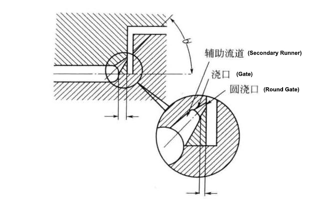
Submerged Gate
Submerged gates are shown in the figure above. Usually, the gate is located on the parting surface of the mold, but with a submerged gate, only the runner is located on the parting surface.
The gate is usually located on the moving plate or stationary plate of the mold, and sometimes on the cavity. Although it is not much different from the pin gate, one advantage of the submerged gate is that it can even be used in two-plate molds.
When the molded product is ejected, the gate automatically falls off.
Gate Balance
For multi-cavity molds, it is very important to achieve gate balance so that each cavity is filled with plastic melt evenly. As the molten plastic flows from the inlet to the end of the mold cavity, the polymer pressure decreases accordingly.
Therefore, gate balancing should optimize the length, width, and depth of the gate. Proper gate and runner balancing design can avoid molding defects during the actual molding process of multi-cavity molds, such as flow marks, shrinkage, underfill, dimensional fluctuations, and weight variations.
Precautions
The basic factors to consider for gate positioning include: part design, flow characteristics, and end-use requirements of the product.
The following points should be kept in mind:
- Large parts requiring multiple gates should have sufficiently tight gates to reduce pressure loss. This minimizes cooling at the resin flow front junction, thus providing better weld line strength. Appropriate gate sizes should be selected to ensure reasonable pressure and velocity of resin filling.
- The gate transition section length should be kept as short as possible.
- Bump gates help ensure that the incoming fluid is directly against the mold cavity wall or core, thus avoiding swirl marks.
- To avoid air trapping, air from the resin flow at the gate should be directed to venting channels.
- The gate location should be carefully determined to allow resin to flow from thick-walled sections to thin-walled sections; minimize weld lines; and keep it away from impact and stress zones.
- To minimize swirls, radial spots, and gate white spots, the gate should be at a suitable angle to the runner.
- Direct pouring onto decorative surfaces will cause surface defects.
Contact Person: Alex
WhatsApp/ WeChat: 0086 18968677763
Email: sc10@solidcomould.com
Website: www.solidcomould.com


